The South Adams signal debacle
After recent changes to increase the current capacity of the DCC system were implemented, several signaling problems developed relating to capacitive inductance. This article will attempt to explain the phenomena and show how the problem was overcome.
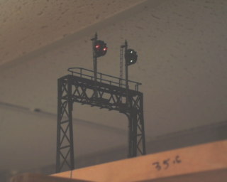
Above you see the South Adams signal, with the switch lined for a straight route from main track to main track. There is no train ahead in either of the two distant blocks, so a clear signal is the normal expected indication. Unfortunately, because of the capacitive inductance problem, the signal would periodically, and without apparent reason, flash an approach aspect momentarily, before returning to clear. It would do this randomly as a train moved around the layout and was quite befuddling. In order to understand the problem, it is first necessary to understand the basic principle behind the signaling system on the Moose Valley. The Moose Valley uses current sensing for train detection. The principle of current sensing train detection, is that a circuit will detect when current is flowing through the rails on the track. Normally, when no train is present, the voltages present on the rails represent an open circuit. Without a train in the affected block, current cannot flow. Once a train enters the block, it is similar to closing an electrical switch, and current can now flow from one rail to the other through the lights and electrical apparatus in the locomotive, be it DCC decoder, or just a conventional DC motor. The wires that carry the electricity to the rails, must pass through a block detection circuit which detects the current draw of a train in the block. On a DC only layout, what we are about to discuss is not possible, but with DCC the behavior I am about to describe is possible.
Under certain circumstances, of wiring, wiring placement, alignment of the track, and other layout features, the DCC signal being applied to the rails, can generate sufficient electrical pulses, as to induce a current in the circuit even though there is a sufficient air gap between all electrical polarities involved. This electrical phenomenon produces undesired operation, and can be a challenge to remove. It is easiest to think of it as Radio Frequency emissions and deal with it accordingly. In essence every wire in the railroad which conducts current, becomes a radio transmitting antenna, and every other circuit with wiring not related to the DCC wiring, can become a radio receiving antenna. Just like when your listening to a weak radio station, the movement of your body in the room can affect reception, the same is true with this problem as the trains and people move about in the layout room. A visual of some kind will be useful at this point, so please refer to the below picture.
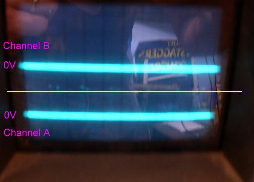
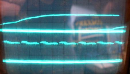
The above is a picture of an Oscilloscope configured to show two separate electrical signals. The blue lines are called scope "traces", and move up and down in relationship to changes in the voltage applied to the scopes probes which are connected at the electrical points being monitored. The top trace, channel B, is the output of the block detector board. When it goes high (to some voltage near or above 8 volts), the signal at South Adams will display approach. It is this trace that is moving against the design wishes of the circuit, and it is this trace that will jump to that high reading whenever the phenomenon occurs. The lower trace, channel A, is the signal which is connected more or less, directly to the track. It is the signal that will be the "radio receiver" in our particular problem. Right now, track power is off, and both lines are very clean and normal looking. Now we will turn track power on, and start a train moving.
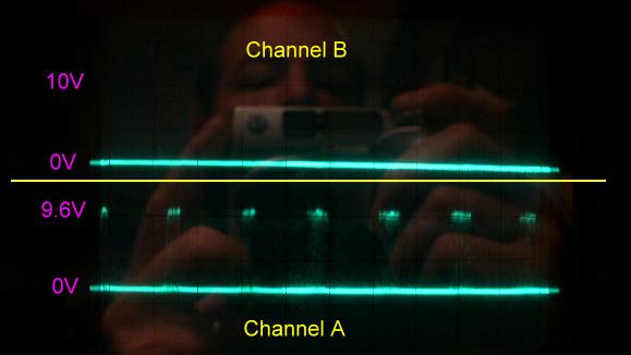
Ah! What has happened? We now have "blips" or spikes of electrical current floating on top of our Channel A signal. These blips look very similar to the nature of the DCC voltage which is neither DC, nor AC, but is a modulated square wave of uneven duration. We can from the blips, that they probably coincide with the sudden changes in polarity of the DCC signal. According to the Channel B trace, they are not currently causing a problem. Let's see what happens as the train moves around the room.
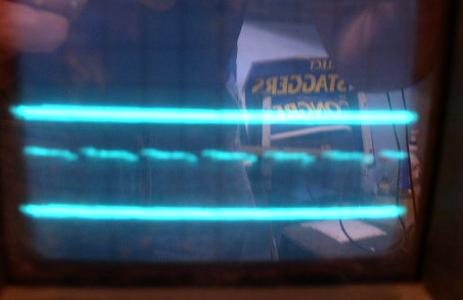
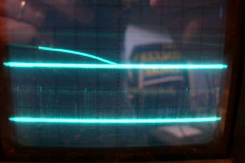
We can now see that the blips are varying in intensity and duration. You can see some visible streaking between the blips and the line below, which is our base signal of 0 Volts. The streaking indicates that the signal is oscillating very fast between 0 volts, and the voltage level of the blips. Due to the design of the detector circuit, a capacitor is slowly charging as it saturates with these voltage spikes. Since the spikes come and go and die off, varying between the two images above, it becomes a matter of timing now before the image below happens.
What you now see is a combination of what really happened, and what the digital camera, with it's slow recording time, was able to record. The blips have now reached an intesity and duration sufficient to saturate the capacitor, and drive the output of the block detector board to "high", causing our signal at South Adams to flip to approach. The picture shows really three passes of the scope trace. In the first pass, the normal thick blue line at the top is stationary. In the second pass, just as the trace "scan" is to the right edge of the screen, there is a sudden jump in voltage. In the third pass, we see that line continuing to ascend as the voltage increases over a few milliseconds.
Then, just as quick as it started, the blips decrease within a second or so, and the output normalizes.
Above you see the detector output voltage drop as the blips become greatly diminished, and return to the nominal "hash" type interference. The top line arcs down from a point at which the camera began recording, and through an additional scan of the trace.
Finally, in the picture below, we see what happens just as a train enters the problem detectors territory.
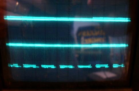
Our detector output goes high as intended, as doest the bottom signal which is what causes the output to go high in the first place, but look at the blips.... they are now inverted, as the interference happens in the reverse direction too. Remember that DCC is bipolar!
To solve this problem, a capacitor was added to the circuit, affecting the output picked up by Channel A. I did not record any photos of the output after the modification, as it did solve the problem, but it did not remove the cause. The capacitor simply reshaped the blips, and limited their amplitude, avoiding saturation of the capacitor downstream.
In summary, DCC is still trying to affect the entire signal system in this manner. It is only the placement of wiring, and other circumstances which is currently preventing this problem from becoming more wide spread.