Backshop Report
Project 133
By Mel Agne
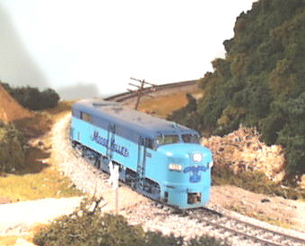
This project deals with repowering, and equipping a Life Like Proto 2000 HO scale FA-2 with a motor from Kato, and a Soundtraxx DSD-150 Alco Diesel Sound DCC Decoder.
I have always liked the Life-Like Proto 2000 FA-2, and even though it was one of the earlier Proto 2000 (P2K for short) models, it still represents one of the better detailed cab units available out of the box today. While the P2K drive is acceptable, I wanted to attain something better, so that this unit would run reliably with other Kato brand products. Also, the drive train and motor of the P2K unit is a little noisy, and with the sound unit on-board, I wanted to reduce the extraneous noise as much as possible. I had on hand, a Kato RS-11 which had hit the floor previously, and was now a parts source. So I decided to try and repower the FA-2 with parts from the RS-11. Since the flywheels on the Kato motor are too long to clear the frame, I replaced them with Northwest Shortline flywheels. These press-fit onto the shafts, and you need to be careful that you set them on as far as possible without rubbing. After installing the flywheels, place a NWSL universal drive shaft coupling onto the ends of each shaft. They should recess into the flywheels.
Completely disassemble the FA-2 until all you have is the frame. I cleaned the truck bolsters until they were oil-free, as this is one of the basic problems of electrical pickup with Athearn style (the P2K line uses many of Athearn's designs) equipment. I used the Kato motor in its original plastic mountings. These mounts hold the motor at the ends, and are tapped for a threaded screw in the bottom middle. It works out that these holes are at the very edges of the fuel tank casting in the bottom of the locomotive. I located the holes in the center at the junction with the fuel tank, and then milled away sufficient material for the screw heads to clear.
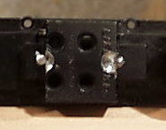 I used 2-56 screws to secure the motor in the frame. After it is in
place, you can remove any excess material from the top of the mounts, especially the ears
that originally held the Kato circuit board, as these will interfere with locating the
decoder. After the motor is mounted, turn your attention to the trucks.
I used 2-56 screws to secure the motor in the frame. After it is in
place, you can remove any excess material from the top of the mounts, especially the ears
that originally held the Kato circuit board, as these will interfere with locating the
decoder. After the motor is mounted, turn your attention to the trucks.
Totally disassemble the trucks, taking care not to break the sideframes that are press-fit into the truck body. Observe the black plastic "vanity plate" that fits between the truck frame and the sideframe. This is a nice touch over an otherwise stock Athearn truck which hides the shiny metal when in place. You will want to re-use these. Replace the wheels using NWSL 40" nickel silver replacement wheels, retaining the original gear and bearings. Use an NMRA guage to set the wheel spacing accurately. Clean all the gears and truck parts in a solvent such as alcohol or mineral spirits, then blow dry. Re-assemble the trucks, but leave the worm gear and tower retainer off. Check the trucks for free-rolling qualities on a piece of track. Observe any binding, and correct. A good source for information on enhancing and troubleshooting Athearn style trucks is the book "Model Railroading with Athearn Locomotives and Cars" by Rocky Mountain Publishing, the presenters of "Model Railroading" magazine. After the truck checks out, solder some small gauge flexible wire to the truck bolster edge, and top bracket. These will carry power directly to the decoder, as we will not rely 100% on frame to bolster conductivity to ensure maximum continuity.
Place the trucks under the frame, and verify that the wires will be clear of pinching or binding. Now remove the plastic coupler from the end of the P2K worm shaft, and retain the bearings. Take the Kato worm couplings, and drill them out to accommodate the larger size P2K worm shaft. Use care and select a drill bit just smaller than the shaft. Now, before pressing the Kato coupler on, lay the worm in the truck tower, and shim it to position the worm at the outer limits of the gear tower. In other words, as far away from the motor as they can get. This is because the top of the gear tower doesn't center the drive gear under the worm. Shifting the worm towards the end helps achieve this. Once the necessary number of shims are installed, press the Kato coupler onto the P2K worm shaft. Ensure that the coupler goes on as far as possible, but not so far as to rub the truck retainer clip once it is installed.
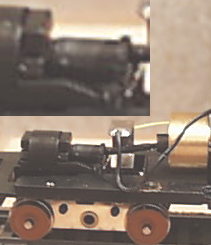 Once your satisfied with the fit of the worm on
the truck, reinstall with the Kato driveshaft as illustrated. Do this for both
trucks. Temporarily connect the wires to the motor, and test run the chassis.
You should get smooth operation with minimal drive shaft noise. If this is not the
case, check for binding or rubbing.
Once your satisfied with the fit of the worm on
the truck, reinstall with the Kato driveshaft as illustrated. Do this for both
trucks. Temporarily connect the wires to the motor, and test run the chassis.
You should get smooth operation with minimal drive shaft noise. If this is not the
case, check for binding or rubbing.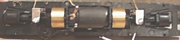
This completes the repowering of the unit.
The next step is to install the decoder and sound system. One of the reasons I selected the FA-2 for sound, was the natural speaker grill that ALCO provided in the form of that nice big fan over the back of the unit. The intake grills on the Life-Like model, also provide a nice opportunity for sound to escape. In addition, the platform used to hold the operating fan makes a nice place to put a speaker. I used a 1" speaker from Soundtraxx. Experimentation showed that this speaker will fit nicely into the shell, provided that a clearance issue with the air intake grills is worked out. I didn't want to mount the speaker in the shell, as I prefer what I call a "unitized" chassis. Meaning that no wires run between the shell and chassis. This allows, in my opinion, an easier to service engine. Consequently, I have gone to some length to make this unitziation possible. If you are content to glue the speaker into the shell, much of what I am about to relate can be ignored.
Begin by removing the air intake grill
assemblies. The assembly consists of two plastic pieces snapped together, which
sandwich the individual movable blades of the grill. The back half, is the part
which interferes with the passage of the fan when the shell is installed or removed.
To reduce the required clearance, replace the back half of the assembly with a
piece of stiff .015 wire. Begin by drilling a hole, just smaller than the wire in
the front half of the assembly at the junction of where the two halves snap together.
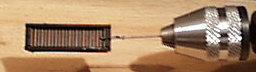 Do
not attempt to disassemble the halves! As this will cause all the grill blades to
fall out! Drill the hole at each end, and then insert the .015 wire through both
holes, so that the back of the grill blades is touching the wire. Leave enough wire
to hang over the ends. Next, retract the wire slightly, in such a way that the wire
is still in the hole, but is now clear of the outer half snap. Carefully free the
back half from the front, then slide the wire through, and repeat for the other end.
Once your finished, your grills should look like this.
Do
not attempt to disassemble the halves! As this will cause all the grill blades to
fall out! Drill the hole at each end, and then insert the .015 wire through both
holes, so that the back of the grill blades is touching the wire. Leave enough wire
to hang over the ends. Next, retract the wire slightly, in such a way that the wire
is still in the hole, but is now clear of the outer half snap. Carefully free the
back half from the front, then slide the wire through, and repeat for the other end.
Once your finished, your grills should look like this. 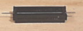 Set the grills
aside. Now modify the fan mount by removing all parts for this mechanism.
Set the grills
aside. Now modify the fan mount by removing all parts for this mechanism.
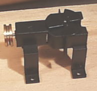 Once the rotating parts are removed, cut away the plastic from the
support until you are left with a mostly flat surface. Use caution with this part,
as the plastic is brittle and cracks will travel easily. I used a pair of diagonal
cutters to do this job, but you will need to plan your cuts to avoid cracking the base of
the structure. Once you have trimmed down the assembly, it may be installed on the
chassis. Proceed to install the decoder by locating it as far forward as possible,
behind the cab wall bulkhead. You may want to paint your crew and cab interior while
your at it. I found that the decoder fit best, if I cut away the pins holding the
original constant lighting assembly, and
Once the rotating parts are removed, cut away the plastic from the
support until you are left with a mostly flat surface. Use caution with this part,
as the plastic is brittle and cracks will travel easily. I used a pair of diagonal
cutters to do this job, but you will need to plan your cuts to avoid cracking the base of
the structure. Once you have trimmed down the assembly, it may be installed on the
chassis. Proceed to install the decoder by locating it as far forward as possible,
behind the cab wall bulkhead. You may want to paint your crew and cab interior while
your at it. I found that the decoder fit best, if I cut away the pins holding the
original constant lighting assembly, and 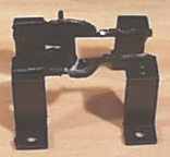 discarded as much
of that plastic as possible. Orient the decoder so that the wires exit it against
the bulkhead, and use cellophane tape to hold the decoder in place. Make your wire
connections according to the decoder instructions.
discarded as much
of that plastic as possible. Orient the decoder so that the wires exit it against
the bulkhead, and use cellophane tape to hold the decoder in place. Make your wire
connections according to the decoder instructions. 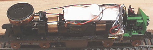 I replaced the original
headlight, with a 16V bulb in a brass tube. Route the wires from the trucks to the
decoder, soldering as needed. Secure all joints with heat shrink tubing. Build
a mount for the speaker out of the bottom of a 1" diameter pill bottle. Cut the
top of the bottle off, so that only 7/16"
I replaced the original
headlight, with a 16V bulb in a brass tube. Route the wires from the trucks to the
decoder, soldering as needed. Secure all joints with heat shrink tubing. Build
a mount for the speaker out of the bottom of a 1" diameter pill bottle. Cut the
top of the bottle off, so that only 7/16" 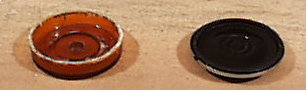 of material remains from the
bottom up. Glue the speaker to the bottle remains with Walthers Goo. Locate
the speaker assembly on the fan platform so that the speaker will be centered under the
fan grill on the body. Lower the body onto the chassis to check for fit and
placement. Since the fan intake grill is still removed, you will have a nice window
to look through to see how things are fitting. Once your satisfied with the fit,
install the modified air intake grills into the body. It will now be necessary to
slightly spread the body as you lower it to get the grills to clear the speaker as it goes
on.
of material remains from the
bottom up. Glue the speaker to the bottle remains with Walthers Goo. Locate
the speaker assembly on the fan platform so that the speaker will be centered under the
fan grill on the body. Lower the body onto the chassis to check for fit and
placement. Since the fan intake grill is still removed, you will have a nice window
to look through to see how things are fitting. Once your satisfied with the fit,
install the modified air intake grills into the body. It will now be necessary to
slightly spread the body as you lower it to get the grills to clear the speaker as it goes
on. 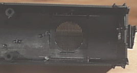 Before applying the body for the final time, cut a piece of thin foam
material about 1-1/4" square, and then make a 7/8" hole in it. glue this
to the body, to act as an insulator between the body and the speaker to prevent vibration
of the fan grill. Test your installation, program, and complete the customizations
of your new ALCO sound equipped FA-2. I highly recommend installing Kadee couplers
using Kadee coupler boxes. Mount them by drilling and tapping the provided
indentations in the frame. I used boxes from a #32 coupler, and one of the Kadee
couplers with a high shank mount, as the couplers will be too high if you use a
number 5.
Before applying the body for the final time, cut a piece of thin foam
material about 1-1/4" square, and then make a 7/8" hole in it. glue this
to the body, to act as an insulator between the body and the speaker to prevent vibration
of the fan grill. Test your installation, program, and complete the customizations
of your new ALCO sound equipped FA-2. I highly recommend installing Kadee couplers
using Kadee coupler boxes. Mount them by drilling and tapping the provided
indentations in the frame. I used boxes from a #32 coupler, and one of the Kadee
couplers with a high shank mount, as the couplers will be too high if you use a
number 5.