
Backshop Report
Project 4259
By Mel Agne
This project deals with a methodology of installing Digitrax decoders in Athearn hood units, that I find appealing for several reasons. First of all, the DH-140 decoder features a detachable wire harness via a low profile header connector. This makes it very easy to replace in the event of failure, with no need to de-solder any connections. Unfortunately, this still involves disassembly of the locomotive, and if you like to detail yours like I do, this can be a dreaded thought. I wanted to try to utilize the removable dynamic brake housing as a way to access the decoder, so that if replacement were necessary it would not require disassembly of the unit. As it turns out, this is easy to accomplish, and adds to the ease of installation. Another thing about this method that I like is the parallel between putting the decoder in the dynamic brake housing, and the idea that real dynamic brake housings hold electrical equipment that generate heat. Most of Athearn's second generation scale hood width GP and SD series locomotives feature this removable panel, regardless of dynamic brakes or not. Although I have not tested it on non-dynamic units, I would guess that this method would still be applicable. Our unit for this discussion is an Athearn GP-40-2, factory painted in the WM version of the Chessie System. Please note that I have already modified the nose and pilot, and that this discussion will not delve into super-detailing or painting, but will only discuss items relevant to the installation of the decoder and lighting.
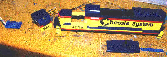
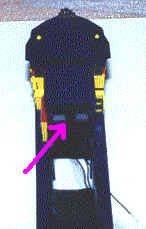
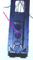
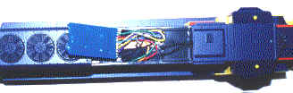
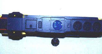
The above photo shows the decoder (left), cab and body with the
dynamic housing removed.
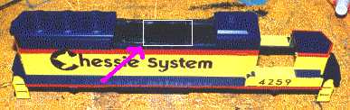
The first step is to enlarge the hole already present in the
panel recess. Using a Dremel tool, or sharp knife, cut the hole to the size
indicated by the white box above. Use the DH-140 decoder as a reference.
Remember, the goal here is to be able to mount the decoder face down (Digitrax logo on the
bottom, mostly flat side of the decoder on the top) with the connector facing
forward. Adjust the size of the hole until the decoder fits snugly over the hole.
Be careful not the cut the hole so large that the decoder falls down in. You
can test your success by trying to put the dynamic brake housing back on. It must
snap into place with the decoder inside without bulging or lifting up.
Because the DH-140 is an FX style decoder, I wanted to make use
of all of the lighting features. This means my unit will have front and rear lights,
classification lights, and (as on the prototype for WM4259) roof mounted strobes.
I choose to install the headlight bulbs directly in the holes
provided by Athearn for the headlight lenses. The 12 volt bulbs must be wired in
series so as not to generate so much heat that they melt the holes that they are in.
The roof top strobes are T-3/4 LED's mounted directly on the roof. The LED's
are wired in Parallel with a 1K resistor feeding them. Keep in mind that the Blue
wire from the decoder (light common) is actually the V+ from the decoder, which means that
all of the decoder functions are really ground paths. Be sure to wire your LED's up
in such a way the the Anode goes to the blue wire. The resistor can be before or
after the LED's in the circuit. The Digitrax manuals provide answers to your
questions about LED and lamp wiring if you have any. When finished this step, you
should have 3 wires sticking out. A common (that will go to the V+ blue wire), one
for the headlights, and one for the strobe lights.
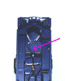
Next, install the cab (but don't put in on all the way yet) and
feed the wires from the cab through the rectangular hole at the front of the dynamic brake
cavity. This hole IS used by the housing, but is large enough to accommodate our
wiring.
If your going to have operating class lights, and like to use
T-3/4 red LED's like I do, then you will need to drill out the class light locations with
a number 50 drill bit.
The T-3/4 LED's are pretty small, and a bit of a challenge to
install, but a drop of super glue will hold them in nicely. Make sure you glue them
in in such a way that the polarity of each is on the same side. This will make
wiring a bit easier.
First, snap the cab on all the way if you haven't done so
already (you need to consider what your going to do with window glazing, weathering, dull
coating etc, before you do this, as the cab will not be removable after this step).
Run a wire from the Anode of the front class light LED's to the common (blue wire)
connecting point already established in the cab roof. Connect another wire to the
Cathode side of the LED's (don't forget the 1K resistor somewhere) and route it through
the front dynamic brake housing rectangular hole.
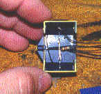
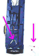
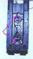
Do the same for the rear class lights. The resistor used
is clearly visible in this photo.
Next, add the rear headlights (wired in series and mounted in
the holes). You could use a single bulb and the Athearn lenses if you prefer.
Configure the wires as you did in the front, and you will have 3 wires sticking through
the rear dynamic brake housing panel rectangular hole.
Prepare the chassis according to established procedures (motor
isolated from frame, trucks wired, Athearn headlight bracket removed), and leave plenty of
wire loose.
Next, position the body over the chassis, and bring the motor
and truck wires up through the hole in the roof. Trim all the wires to reasonable
lengths, and connect the decoder using Digitrax instructions. Remember that you have
two common (V+ Blue wire) feeds from the front and rear of the shell to connect to the
blue wire. The DH-140 only has 4 functions, so you will have to decide which one
does what, but I choose White - Front headlight, Yellow - Rear Headlight, Green - Roof
strobes, and Purple - Class lights (both front and rear connected together).
Alternately, you could connect the rear class lights to the white wire with the front
headlight, and the front class lights to the yellow wire with the rear headlight, so that
the traditional display of red markers on the rear while going forward with the front
headlight on would be evident. Or, you could connect the front class lights directly to
the purple, leaving the rear class lights connected to the front headlight (white)
wire. This makes for a neat effect when your locomotive is operating as a pusher
facing backwards - Just like on Sandpatch! Or rather I should say just like they
USED to, before CSX ripped out all the class lights!
Make sure you have the body on all the way now. Begin
stuffing all those wires (which you properly soldered and covered with heat-shrink tubing)
into the body cavity. Pushing them forward with tweezers seems to work well.
Once stuffed, they should allow the decoder to rest in place
like it did when you were test fitting it earlier. Don't put the housing back on
yet. The dynamic brake housing looks like it might get loose with too much
installing and removing, so don't test fit yet.
Go ahead and test run your engine. Take a moment to
program the decoder, and get those strobe lights flashing the way they should. Run
the engine with all of the functions turned on and watch for excessive heat, or mechanical
problems. While it's making some laps around your layout, you can do the next step
which is optional.
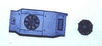
Since decoders do generate some heat, I thought it might be
nice if that heat could escape easily. I had a 48" fan left over from a
Life-Like Proto 2000 GP-18 that is slightly different from the one included on the Athearn
model, but the thought of a little fan blade that will really spin (if you blow on it),
and the ability of the decoder to vent heat up through the fan (just like the real thing!)
over ruled any desire for 100% prototypicallity. Besides, who says somebody in
Cumberland didn't have to replace the fan on 4259 at some point in it's life? Don't
think for a minute that the shops wouldn't substitute a different model fan if they had
to.
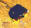
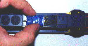
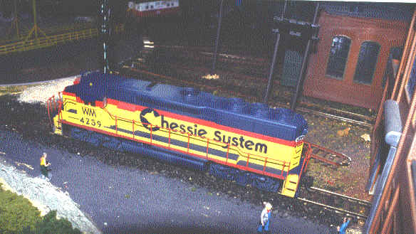
After removing the cast-on fan, go ahead and fetch your engine
(which you left testing on the layout) and put the dynamic brake housing on. The
decoder is now clearly visible through the hole. If you made the hole the right
size, your replacement fan will now press-fit, and it won't require any glue.
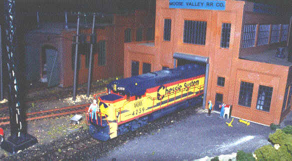
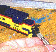
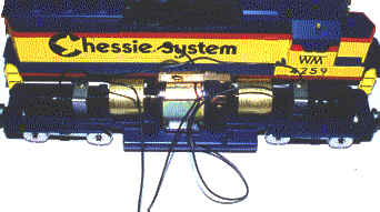
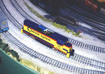
Here we see WM 4259 rolling out of the Moose Valley's Berkeley
shops, after being serviced and upgraded with what the Moose Valley refers to as
"Dynamic Consist Control" (Sounds more railroady than DCC). That little
fan that spins when you blow on it will keep that nice Digitrax DH-140 cool and
ventilated, and if it ever does fail, it will only take 1 minute to replace it without
disassembling your entire model.
Happy Railroading!